How To: Wire up Elmo Live to a computer!
12/16/2009
 Last year was the first annual Wishzilla Seven Candy Cam, which included fun toys to play with over the Internet. The star of the show was the new (at the time) Elmo Live, with fun stories and quirky actions that were perfect for viewing and listening to on our live webcam.
This year, Elmo was back on stage, but suffered a seizure after being run continuously for about a week. He would start talking and just freeze up. So we took him apart and tried to see if it was something obvious, to no avail. We would have to get a new Elmo.
The problem with this is that in order to hook him up to the computer we had to add some wiring to allow the computer to close the various switches that make Elmo so much fun to play with. Since we already did it once last year, we decided to put together this little how-to.
What we are accomplishing
This how-to is about wiring up all of Elmo's switches to allow them to be hooked into some sort of computer interface. In our case we are using an Arduino, but the actual interface to the computer will be the subject of a future how-to.
Opening up Elmo
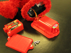
Remove the foot insert
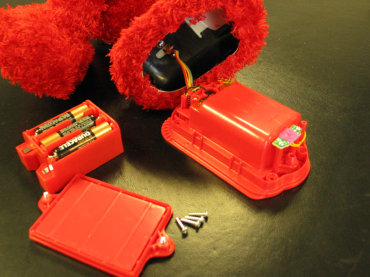
The first step is to remove the battery pack and Elmo's left foot insert. Just remove the four screw
The next step is to find the seam that runs up the middle of Elmo's back. There is a single large red thread that holds the seam together, and if you tug the seam apart and wiggle it a bit, you should see a strong red thread that looks a little different. They did a good job of matching the color, so this can be a bit tricky! Once you find it, clip it and open up the seam. It's not necessary to undo the seam around Elmo's neck, so be careful not to clip those threads.
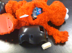
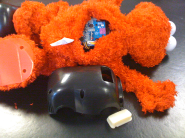
Mid-surgery: Elmo's back removed
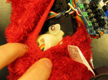
Find and remove the six screws that hold the main body together, and carefully remove the back shell and switch button. You should be able to do this without cutting or unstitching any other seams. Remove the main circuit board by taking out the three screws.
Be careful when you have Elmo this far apart. The circuit board and back case actually hold his top and bottom together.
Wiring Elmo Up
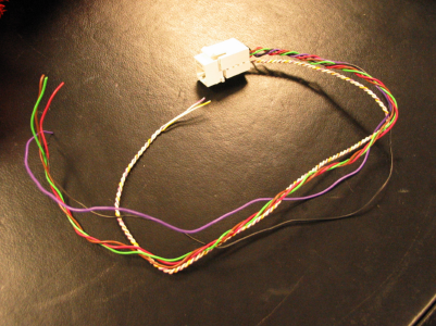
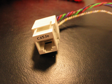
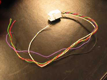
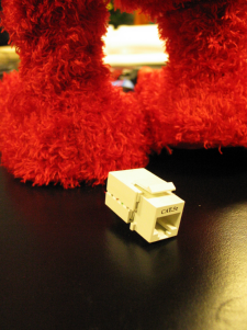
We can fully control Elmo with an umbilical that has seven conductors: two for the speaker, four for the switches, and one for ground. Conveniently, CAT 5 has eight conductors, so using a CAT 5 jack makes it easy to just use any old CAT 5 patch cable to connect Elmo to the Arduino. Here is a picture of the umbilical terminated into a standard CAT 5 keystone jack. We used some 27 gauge wire for this purpose, although you could probably just use some CAT 5 cable.
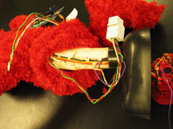
Wires fed through
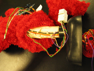
Feed two conductors down into the foot, and the remaining five up the leg and through the hip joint as shown.
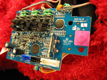
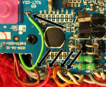
Get your soldering iron warmed up. We still want Elmo to work as normal, mostly, so we don't want to actually desolder the wires to the various switches. I just stripped about 1/8" off the end of each wire and was able to push each wire through the circuit board contact point once the solder was melted. Identify the various switches on the circuit board. The nose and belly correspond to S1 and S4 respectively on Elmo Live Encore (on Elmo Live they are actually labelled by what they are, so that makes it easy). The back switch is available via a small contact point right below the switch on the board. On Elmo Live Encore, this is just a contact point on the board, but on Elmo Live it is actually a hole (or "via") in the circuit board.
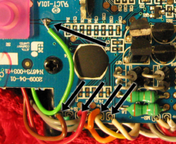
Elmo wired up
Solder a wire to S1+, S4+, and the center contact point below the back switch. If you want Elmo's internal speaker to still work, make sure to keep the original SP+ and SP- wires soldered in place while adding the external speaker wire. We have Elmo hooked up to the website, and as much as we like him he drives us nuts with all the people playing with him. I just removed the SP- wire and left it disconnected so the sound only goes over to the computer.
Elmo's foot is a little trickier. Just feed the two wires you fed into the foot casing around to the little circuit board that the foot switch is attached to. If you are using Elmo Live, we discovered that the polarity is switched. Connect your common ground wire to the + side if you are using the original Elmo Live. They fixed this on Elmo Live Encore, so the common ground wire should go to the - side of the switch. Be careful to route the wires through the foot carefully, keeping them away from the screw holes.
Putting him back together
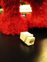
Elmo wired up
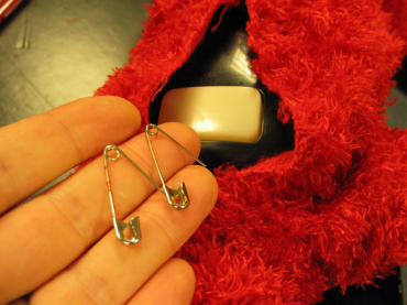
Screw the main circuit board back into place and replace the back shell. If the holes don't line up, move the legs forward or back a bit until they do. I had trouble keeping the back switch from falling out when I was putting the back together again, so I just used some blue masking tape to hold the switch in place (from the outside, of course). To make it easy to access the wiring again, I just used a couple of safety pins to hold Elmo's suit on.
Put the foot back together, making sure to route your umbilical out the back. You should be able to do this without cutting the fabric or anything. We want to keep Elmo as pristine as possible!
That's about it! Elmo is now ready to get hooked up to the computer. You can test him out by pressing all four switches normally, and by closing each switch wire to the common ground manually using a CAT 5 cable with one end stripped off. Elmo is now ready to be actuated remotely. Give him a try on the Seven Candy Cam.
Image Gallery

